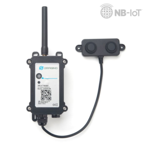
Changing the Uplink interval:
To change the uplink interval of the device you will need:
– A USB-TTL Converter
– 3 M-F Cables
– A Phillips screwdriver
Via AT Command
- Open up the device by removing the 4 screws on the front of the device.
- Using the M-F Cables, connect the female end of the cables to the USB-TTL Converter as shown below:

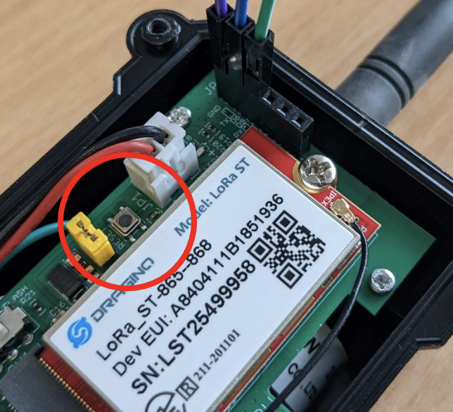
- Then connect the male end of the cables to the corresponding pin receptors on the device as shown below:
USB-TTL GND –> Device GND
USB-TTL RXD –> Device TXD
USB-TTL TXD –> Device RXD

- Plug the USB-TTL Converter into a USB port on your laptop and open Serial Port Utility. If you have a Windows laptop it should already be installed, if not you can install a copy here.
- On the left hand side, select the COM Port that you have plugged the USB-TTL converter into and make sure the rest of the fields match that of the image below:

6. Click the play/start button to open the session, then hit the reset/join button on the device.
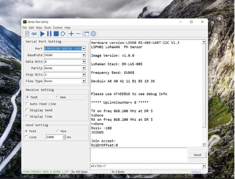
- To begin communicating with the device you will first need to enter the device password (12345/123456 as default for older models, or the AT PIN provided on box for newer models e.g. SPH01-LB/NB).

- To see the current uplink interval use the AT Command: AT+TDC=?. Make sure to leave a new line after every AT Command entered. The device should then show 1200000 OK if the device is set to a 20min Uplink interval.

- To change the uplink interval enter: AT+TDC=’the required uplink interval in milliseconds’
For Example:
- AT+TDC=30000 – To change the uplink interval to 30 seconds
- AT+TDC=60000- To change the uplink interval to 60 seconds

- The device will reply with ‘OK’. Then hit the reset button on the device to trigger this change. You will see an uplink then come through serial port utility every 30 seconds.

- Once the calibration is complete, you can then return the device to a 20min uplink interval by entering the command: AT+TDC=1200000 and then hitting the reset button on the device.

- You can check that this has worked by entering the command AT+TDC=?. If the device sends the response: 1200000 OK, then you have successfully returned the device to its original uplink interval of 20mins.

Calibrating the Device:
To calibrate the device you will need:
– A USB-TTL Converter
– 3 M-F Cables
– A Phillips screwdriver
– Distilled Water
– 4.01, 6.86, 9.18 pH Buffer Solutions
Via AT Command
- Follow steps 1-10 above to set the uplink interval of the device to 30 seconds.
- Clean the probe end in distilled water. Do this between each buffer solution.
- Place the probe into the first buffer solution (pH 4.01) making sure the probe is fully submerged.
- In serial port utility you will be able to see the pH that the device is reading as shown below (this happens automatically when the device sends an uplink):

- Allow the device to complete a few uplinks to make sure that the reading is stable.
- To calibrate the device to the 4.01 buffer solution, enter the AT Command: AT+PHCAL=4

- Allow the device to complete another uplink to check that the pH Value matches that of the buffer.
- If it does then you can remove the probe from the buffer and repeat steps 2-7 for the 6.86 and 9.18 buffer solutions remembering to clean the probe in between each calibration. The AT Commands are as below:
| pH Buffer Solution: | AT Command: |
| 4.01 | AT+PHCAL=4 |
| 6.86 | AT+PHCAL=6 |
| 9.18 | AT+PHCAL=9 |
- Once the calibration is complete, carry out steps 11-12 from the previous section to return the device to a 20min uplink interval and set these values.