Contents
Upgrading the Firmware
How you do firmware upgrades will differ between devices. See the sections below to find the instructions for your device.
1.0 Gateways
This includes the following devices DLOS8N, LG308N, LPS8N, LPS8V2 & LG01V2. This will also be correct for the cellular versions of these devices.
1.1 Access & Configure Web UI
Open a browser on your PC and type the gateway IP address (this will differ depending on your connection method):
http://10.130.1.1/ (If accessing the device via Wi-Fi AP network)
or
http://IP_ADDRESS or http:// IP_ADDRESS:8000
You will see the login interface of the gateway as shown below.
The account details for the Web Login are:
Username: root
Password: dragino

1.2 Upgrade Firmware
From the menu displayed along the top of the gateways web console select System > Firmware Upgrade.

Click “Choose File”. Select the firmware file and click “Upload” (The latest firmware files can be found here).

Note: The preserve settings checkbox should be unticked as this may cause issues when downloading the new firmware version.
The system will then reboot with the new firmware after the upgrade has been completed.
2.0 Sensors
2.1 SN50V3 Board Type
This includes the following devices SN50v3, D2X-LB, S31X-LB, CPL01, DSO3A-LB, WL03A-LB, SW3L-LB Series, DDSXX-LB, LDSXX-LB, MDSXXX-LB, LMS01-LB, SE01-LB, SPH01-LB, RS485-LB and the NB versions of these devices.
To access the device to upgrade the firmware you will need:
– A USB-TTL Converter
– 3 F-F DuPont Cables
– A Phillips screwdriver
- Open up the device by removing the 4 screws on the front of the device.
- Using the F-F Cables connect one end of the cables to the USB-TTL Converter as shown below:

Then connect the other end of the cables to the corresponding pin receptors on the device as shown below:
USB-TTL GND –> Device GND
USB-TTL RXD –> Device PA2
USB-TTL TXD –> Device PA3

- Plug the USB-TTL Converter into a USB port on your laptop and open Tremo Programmer.
- Turn the device on using the yellow jumper. The switch the ISP-FLASH switch to ISP and hit the RESET/JOIN button to confirm.

- In Tremo Programmer, select the device port to be connected, baud rate (as shown here) and .bin file to be downloaded. The latest Firmware version can be found here.

- Click Start. When you see the below dialogue page, this means that the firmware has been downloaded.
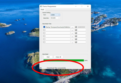
- Switch the ISP/FLASH switch back to FLASH and hit the RESET/JOIN button again to confirm.
- You can test if the upgrade has been successful using Serial Port Utility.
- In Serial Port Utility, select the device port to be connected, baud rate and parity as shown below. Click the “Play” button to connect.
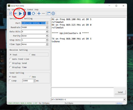
- Then enter the devices AT Pin in the command section (this can be found on the registration key sticker on the device box), press the enter key and then “Send”. You can then enter the AT Command “AT+VER=? ” in the command section as below. Press the enter key and then “Send “, the device should then reply with the firmware version of the device and OK as below.

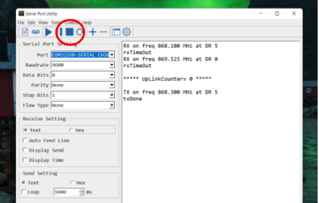
- 15. Once you are happy with this, disconnect from Serial Port Utility using the “Stop” button and unplug the USB-TTL Converter from your laptop.
2.2 LSN50 Board Type
This includes the following devices LSN50v2-8, LSN50v2-D2X, LSN50v2-S31X, CPL01, LDSO3A, LWL03A, SW3L Series and the NB-IoT versions of these devices.
To access the device to upgrade the firmware you will need:
– A USB-TTL Converter
– 3 F-F DuPont Cables
– A Phillips screwdriver
- Open up the device by removing the 4 screws on the front of the device.
- Using the F-F Cables connect one end of the cables to the USB-TTL Converter as shown below:
Then connect the other end of the cables to the corresponding pin receptors on the device as shown below:
USB-TTL GND –> Device GND
USB-TTL RXD –> Device PA2
USB-TTL TXD –> Device PA3

- Plug the USB-TTL Converter into a USB port on your laptop and open STM32 CubeProgrammer (Download here).
- Turn the device on using the yellow jumper. The switch the ISP-FLASH switch to ISP and hit the RESET/JOIN button to confirm.
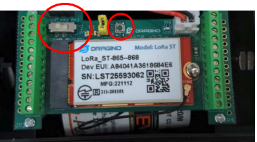
- In STM32 CubeProgrammer, select the device port to be connected, baud rate and parity as shown below.

- Click “Open File”. Select the firmware file and click “Open” (The latest firmware files can be found here).

- Then select “Download” to begin the firmware upgrade.
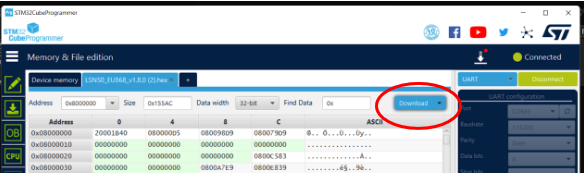
- When you see the below dialogue page, this means that the firmware has been downloaded.

- You can then click “Disconnect” and close the program.

- Switch the ISP/FLASH switch back to FLASH and hit the RESET/JOIN button again to confirm.
- You can test if the upgrade has been successful using Serial Port Utility.
- In Serial Port Utility, select the device port to be connected, baud rate and parity as shown below. Click the “Play” button to connect.

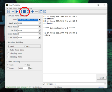
- Then enter the devices AT Pin in the command section (default password is 12345 or 123456), press the enter key and then “Send”. Then enter the AT Command “AT+VER=? ” in the command section as below. Press the enter key and then “Send “, the device should then reply with the firmware version of the device and OK as below.

- Once you are happy with this, disconnect from Serial Port Utility using the “Stop” button and unplug the USB-TTL Converter from your laptop.
2.3 Board Type 2
This includes the following devices LTC2-XX, LDDSXX, LLDSXX, LMDSXXX, LLMS01, LSE01, LSPH01, GroPoint Air, RS485-BL and the NB-IoT versions of these devices.
To access the device to upgrade the firmware you will need:
– A USB-TTL Converter
– 3 M-F DuPont Cables
– A Phillips screwdriver
- Open up the device by removing the 4 screws on the front of the device.
- Using the M-F Cables provided connect the female the female end of the cables to the USB-TTL Converter as shown below:

- Then connect the male end of the cables to the corresponding pin receptors on the device as shown below:
- USB-TTL GND –> Device GND
- USB-TTL RXD –> Device TXD
- USB-TTL TXD –> Device RXD

- Plug the USB-TTL Converter into a USB port on your laptop and open STM32 CubeProgrammer (Download here).
- Turn the device on using the yellow jumper. The switch the ISP-FLASH switch to ISP and hit the RESET/JOIN button to confirm.
- In STM32 CubeProgrammer, select the device port to be connected, baud rate and parity as shown below.

- Click “Open File”. Select the firmware file and click “Open” (The latest firmware files can be found here).

- Then select “Download” to begin the firmware upgrade.

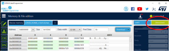
- When you see the below dialogue page, this means that the firmware has been downloaded.
- You can then click “Disconnect” and close the program.
- Switch the ISP/FLASH switch back to FLASH and hit the RESET/JOIN button again to confirm.
- You can test if the upgrade has been successful using Serial Port Utility.
- In Serial Port Utility, select the device port to be connected, baud rate and parity as shown below. Click the “Play” button to connect.
- Then enter the devices AT Pin in the command section (default password is 12345 or 123456), press the enter key and then “Send”. Then enter the AT Command “AT+VER=? ” in the command section as below. Press the enter key and then “Send “, the device should then reply with the firmware version of the device and OK as below.
- Once you are happy with this, disconnect from Serial Port Utility using the “Stop” button and unplug the USB-TTL Converter from your laptop.
2.4 LHT65N/S
To access the device to upgrade the firmware you will need:
– LHT65N Programming Cable (E2)
– USB-TTL Converter
– 4x Male to Female Dupont Cable
– 1x Male to Male Dupont Cable
- First install and open Tremo Programmer
- Using the Male to Female Dupont Cables, USB-TTL Converter and LHT65N Programming Cable, wire up the devices as below:


Male to Female Cables:
USB-TTL GND —-> Programming Cable Port 1
USB-TTL RXD —-> Programming Cable Port 5
USB-TTL TXD —-> Programming Cable Port 9
USB-TTL 3V3 —-> Programming Cable Port 4
Male to Male Cable:
<—-Programming Cable Port 3

- Plug the USB C into the LHT65N. Then using the loose male Dupont cable (in port 3) short circuit port 1. This will reset the device and put it into bootload mode.

- Plug the USB-TTL Converter into your laptop.
- In Tremo Programmer, select the device port to be connected, baud rate (as shown here) and bin file to be downloaded. The latest Firmware version can be found here.

- Click Start. When you see the below dialogue page, this means that the firmware has been downloaded.

- Unplug the USB-TTL Converter from your laptop. Then remove the Dupont Cable from port 4 of the Programming cable.
- Use the loose male Dupont cable (in port 3) to short circuit port 1 to reset the device.

2.5 LHT52
To access the device to upgrade the firmware you will need:
– LHT52 Programming Adapter
– DAPLink-USBC Converter
– 4x Female to Female Dupont Cable
– Small Flat Head Screwdriver
- First install and open Psoc Programmer 3.27.1.
- Using the Female to Female Dupont Cables, DAPLink-USB Converter and LHT52 Programming Cable, wire up the devices as below:

- Downlink the new sensor firmware in preparation- The newest firmware version can be found here.
- Open PSOC Programmer and select the default configuration.
- Click the file icon to select the firmware version to be burned


- Click the download icon, and the progress bar as shown below will appear. When the dialogue “PASS” appears, the firmware upgrade has been successful.


- It is very important to press the reset button after the firmware upgrade. This is to set the device to work in Low Power mode again.
2.6 LDS02 & LWL02
To access the device to upgrade the firmware you will need:
– DAPLink-USBC Converter
– 4x Male to Female Dupont Cable
– Small Flat Head Screwdriver
- First install and open Psoc Programmer 3.27.1.
- Using the Male to Female Dupont Cables & DAPLink-USB Converter, wire up the devices as below:
- GND – DAPLink GND
- VDD- DAPLink 3.3V
- CLK- DAPLink CLK
- DIO- DAPLink SWD

- Downlink the new sensor firmware in preparation- The newest firmware version can be found here.
- Open PSOC Programmer and select the default configuration.
- Click the file icon to select the firmware version to be burned:
- Click the download icon, and the progress bar as shown below will appear. When the dialogue “PASS” appears, the firmware upgrade has been successful.
- It is very important to press the reset button after the firmware upgrade. This is to set the device to work in Low Power mode again.
2.7 LT-22222-L & RS485-LN
To access the device to upgrade the firmware you will need:
– A USB-TTL Converter
– 3 M-F DuPont Cables
– 3.5mm programming cable (provided with devices)
– A Phillips screwdriver
- Plug the 3.5mm programming cable into the PROG port on the device.
- Using the M-F Cables connect one end of the cables to the USB-TTL Converter as shown below:
Then connect the other end of the cables to the corresponding pin receptors on the programming cable as shown below:
USB-TTL GND –> Black
USB-TTL RXD –> White
USB-TTL TXD –> Red

- Make sure your device is powered on. Both the LT-22222-L and the RS485-LN can be powered by a 7 ~ 24V DC power source. If the device is properly powered the Power LED will glow red. See below for connection methods:
RS485-LN
- Power Source VIN to RS485-LN VIN+
- Power Source GND to RS485-LN VIN-

LT-22222-L
- Power Source V+ to LT-22222-L VIN
- Power Source V- to LT-22222-L GND

- Then we need to put the devices into bootload mode. See below:
- RS485-LN
Hold down the PRO button and then momentarily press the RST (reset) button and the SYS LED will change from OFF to ON. When the SYS LED is on, it means the RS485-LN is in bootload mode.
- LT-22222-L
Hold down the PRO button and then momentarily press the RST (reset) button and the DO1 LED will change from OFF to ON. When the DO1 LED is on, it means the device is in bootload mode.
- Plug the USB-TTL Converter into a USB port on your laptop and open STM32 CubeProgrammer (Download here).
- In STM32 CubeProgrammer, select the device port to be connected, baud rate and parity as shown below.
- Click “Open File”. Select the firmware file and click “Open” (The latest firmware files can be found here).
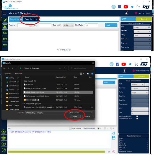
- Then select “Download” to begin the firmware upgrade.

- When you see the below dialogue page, this means that the firmware has been downloaded.
- You can then click “Disconnect” and close the program.
- Switch the ISP/FLASH switch back to FLASH and hit the RESET/JOIN button again to confirm.
- You can test if the upgrade has been successful using Serial Port Utility.
- In Serial Port Utility, select the device port to be connected, baud rate and parity as shown below. Click the “Play” button to connect.
- Then enter the devices AT Pin in the command section (default password is 12345 or 123456), press the enter key and then “Send”. Then enter the AT Command “AT+VER=? ” in the command section as below. Press the enter key and then “Send “, the device should then reply with the firmware version of the device and OK as below.
- Once you are happy with this, disconnect from Serial Port Utility using the “Stop” button and unplug the USB-TTL Converter from your laptop.