Download as PDF
1.0 Accessing the AT Commands
How you access the AT Commands will differ between devices. See the sections below to find the instructions for your device.
1.1 Board Type 1
This includes the following devices LSN50v2-8, LSN50v2-D2X, LSN50v2-S31X, CPL01, LDSO3A, LWL03A, SW3L Series and the NB-IoT versions of these devices. This will also be correct for the upgraded versions of these devices (e.g. SN50V3-LB/NB, D2X-LB/NB, S31X-LB/NB, CPL03-LB/NB, DS03A-LB/NB, SW3L-LB/NB)
To access the AT Commands to change the configuration of your device you will need:
– A USB-TTL Converter
– 3 F-F DuPont Cables
– A Phillips screwdriver
- Open up the device by removing the 4 screws on the front of the device.
- Using the F-F Cables connect one end of the cables to the USB-TTL Converter as shown below:

Then connect the other end of the cables to the corresponding pin receptors on the device as shown below:
USB-TTL GND –> Device GND
USB-TTL RXD –> Device PA2
USB-TTL TXD –> Device PA3
Then turn on the device placing the yellow jumper over both power pins.

Plug the USB-TTL Converter into a USB port on your laptop and open Serial Port Utility. If you have a Windows laptop it should already be installed, if not you can install a copy here.
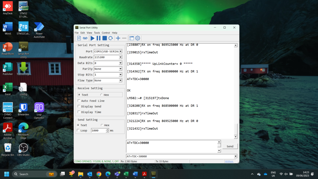
- On the left hand side, select the COM Port that you have plugged the USB-TTL converter into and make sure the rest of the fields match that of the image below:
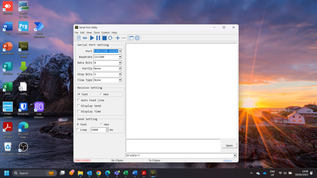
- Click the play/start button to open the session.

- To begin communicating with the device may need to enter the device password (123456 or 12345678 as default- Newer models will have a unique AT Pin which can be found on the registration key sticker on the device box). Make sure to press the enter key before you press send as otherwise to command will not work.
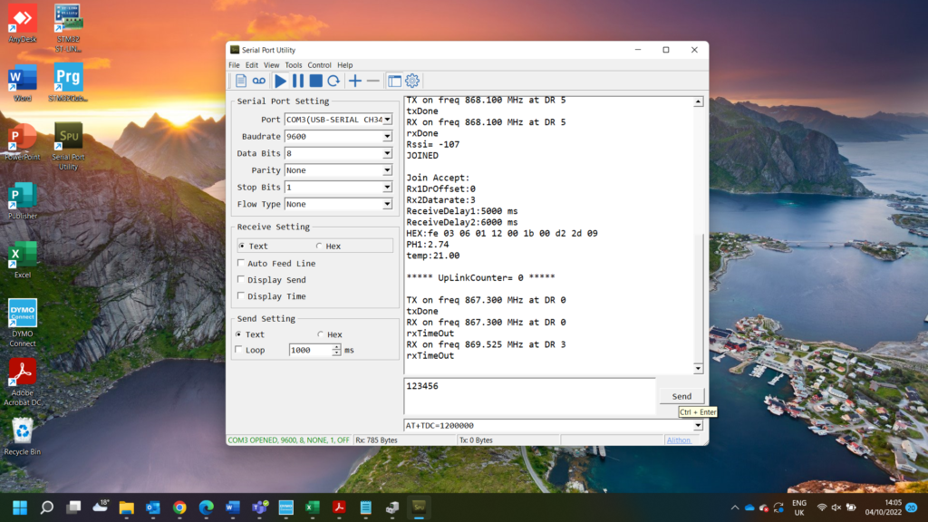
- You can then enter any device specific or common commands to change the device configuration. In this example we will use the AT+TDC=(time in milliseconds) command to adjust the uplink interval.
- To see the current uplink interval use the AT Command: AT+TDC=?. Make sure to leave a new line after every AT Command entered. The device should then show 1200000 OK if the device is set to a 20min Uplink interval.
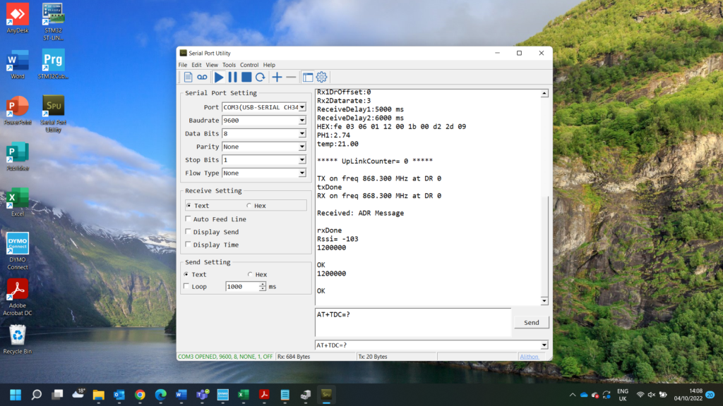
- 10. To change the uplink interval enter: AT+TDC=’the required uplink interval in milliseconds’
For Example:
- AT+TDC=30000 – To change the uplink interval to 30 seconds
- AT+TDC=60000- To change the uplink interval to 60 seconds
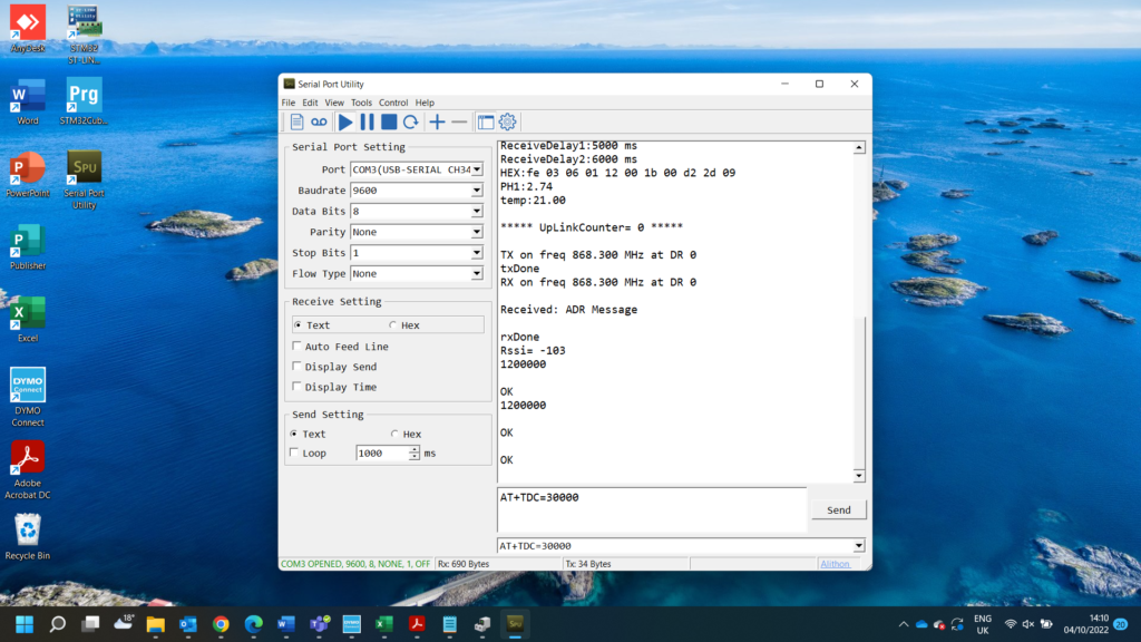
- The device will reply with ‘OK’. Then hit the reset button on the device to trigger this change. You will see an uplink then come through serial port utility every 30 or 60 seconds depending on which command was used.

1.2 Board Type 2
This includes the following devices LTC2-XX, LDDSXX, LLDSXX, LMDSXXX, LLMS01, LSE01, LSPH01, GroPoint Air, RS485-BL and the NB-IoT versions of these devices. This will also be correct for the upgraded versions of these devices (e.g. DDSXX-LB/NB, LLDSXX-LB/NB, LMDSXXX-LB/NB, LMS01-LB-NB, SE01-LB-NB, SPH01-LB-NB, RS485-LB/NB).
To access the AT Commands to change the configuration of your device you will need:
– A USB-TTL Converter
– 3 M-F DuPont Cables
– A Phillips screwdriver
- Open up the device by removing the 4 screws on the front of the device.
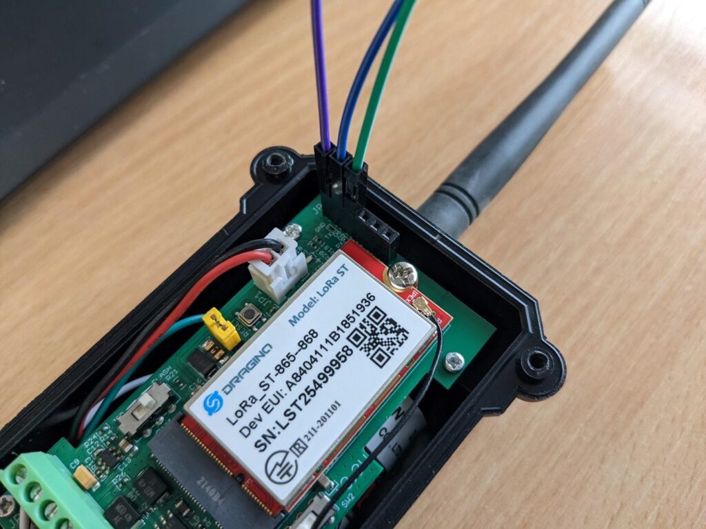
- Using the M-F Cables provided connect the female the female end of the cables to the USB-TTL Converter as shown below:

- Then connect the male end of the cables to the corresponding pin receptors on the device as shown below:
USB-TTL GND –> Device GND
USB-TTL RXD –> Device TXD
USB-TTL TXD –> Device RXD
Then turn on the device placing the yellow jumper over both power pins.
- Plug the USB-TTL Converter into a USB port on your laptop and open Serial Port Utility. If you have a Windows laptop it should already be installed, if not you can install a copy here.
- On the left hand side, select the COM Port that you have plugged the USB-TTL converter into and make sure the rest of the fields match that of the image below:
- Click the play/start button to open the session.
- To begin communicating with the device may need to enter the device password (123456 or 12345678 as default- Newer models will have a unique AT Pin which can be found on the registration key sticker on the device box). Make sure to press the enter key before you press send as otherwise to command will not work.
- You can then enter any device specific or common commands to change the device configuration. In this example we will use the AT+TDC=(time in milliseconds) command to adjust the uplink interval.
- To see the current uplink interval use the AT Command: AT+TDC=?. Make sure to leave a new line after every AT Command entered. The device should then show 1200000 OK if the device is set to a 20min Uplink interval.
- To change the uplink interval enter: AT+TDC=’the required uplink interval in milliseconds’
For Example:
- AT+TDC=30000 – To change the uplink interval to 30 seconds
- AT+TDC=60000- To change the uplink interval to 60 seconds
- The device will reply with ‘OK’. Then hit the reset button on the device to trigger this change. You will see an uplink then come through serial port utility every 30 or 60 seconds depending on which command was used.
1.3 LHT65N/S & LHT52
To access the AT Commands to change the configuration of your device you will need:
– E2 Programming Cable
– USB-TTL Converter
– 3 M-F DuPont Cables
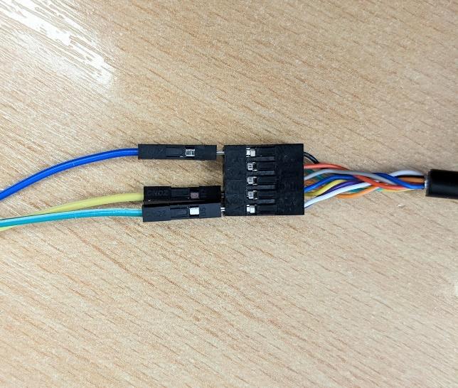
Male to Female Cables:
USB-TTL GND —-> Programming Cable Port 1
USB-TTL RXD —-> Programming Cable Port 5
USB-TTL TXD —-> Programming Cable Port 9
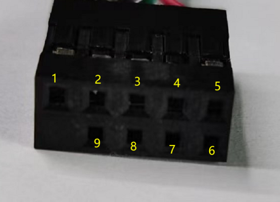
- Plug the USB C end of the programming cable into your device.
- Plug the USB-TTL Converter into a USB port on your laptop and open Serial Port Utility. If you have a Windows laptop it should already be installed, if not you can install a copy here.
- On the left hand side, select the COM Port that you have plugged the USB-TTL converter into and make sure the rest of the fields match that of the image below:

- Click the play/start button to open the session.
- To begin communicating with the device may need to enter the device password (123456 or 12345678 as default- Newer models will have a unique AT Pin which can be found on the registration key sticker on the device box). Make sure to press the enter key before you press send as otherwise to command will not work.
- You can then enter any device specific or common commands to change the device configuration. In this example we will use the AT+TDC=(time in milliseconds) command to adjust the uplink interval.
- To see the current uplink interval use the AT Command: AT+TDC=?. Make sure to leave a new line after every AT Command entered. The device should then show 1200000 OK if the device is set to a 20min Uplink interval.
- To change the uplink interval enter: AT+TDC=’the required uplink interval in milliseconds’
For Example:
- AT+TDC=30000 – To change the uplink interval to 30 seconds
- AT+TDC=60000- To change the uplink interval to 60 seconds
- The device will reply with ‘OK’. Then hit the reset button on the device to trigger this change. You will see an uplink then come through serial port utility every 30 or 60 seconds depending on which command was used.
1.4 LDS02 & LWL02
To access the AT Commands to change the configuration of your device you will need:
– A USB-TTL Converter
– 3 M-F DuPont Cables
– Small flat head screwdriver
- Open up the device by sliding the back off the device and then using a small screwdriver to remove the board and battery casing from the external casing.
- Using the M-F Cables provided connect the female the female end of the cables to the USB-TTL Converter as shown below:
Then connect the male end of the cables to the corresponding pin receptors on the device as shown below:

USB-TTL GND –> Device GND
Then turn on the device by inserting 2x AAA
USB-TTL RXD –> Device TXD batteries. USB-TTL TXD –> Device RXD

- Plug the USB-TTL Converter into a USB port on your laptop and open Serial Port Utility. If you have a Windows laptop it should already be installed, if not you can install a copy here.
- On the left hand side, select the COM Port that you have plugged the USB-TTL converter into and make sure the rest of the fields match that of the image below:
- Click the play/start button to open the session.
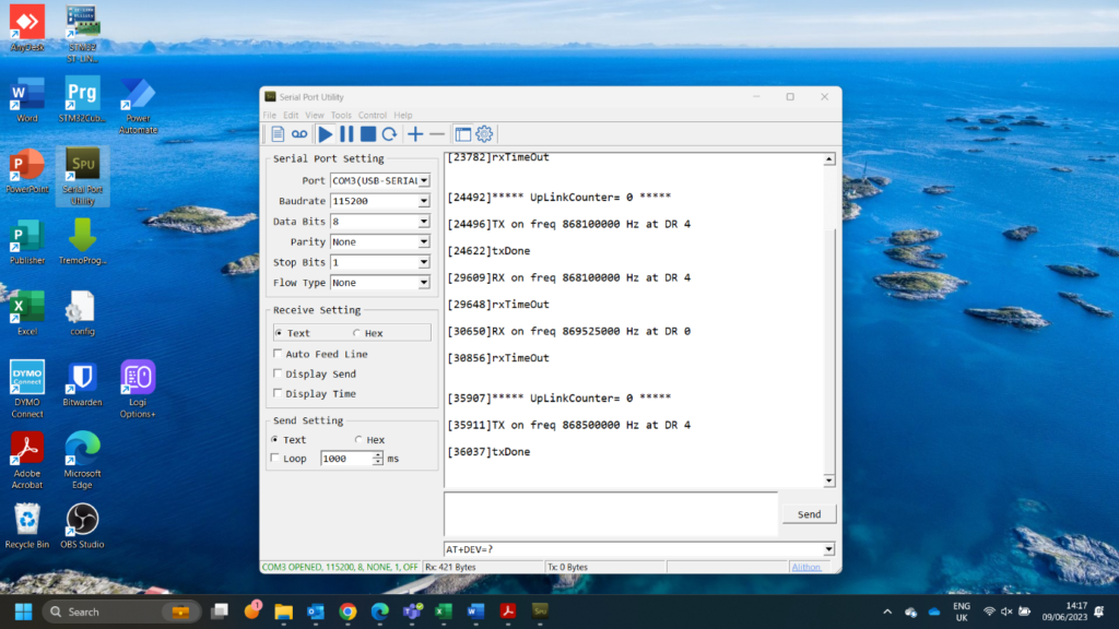
- To begin communicating with the device may need to enter the device password (123456 or 12345678 as default- Newer models will have a unique AT Pin which can be found on the registration key sticker on the device box). Make sure to press the enter key before you press send as otherwise to command will not work.

- You can then enter any device specific or common commands to change the device configuration. In this example we will use the AT+TDC=(time in milliseconds) command to adjust the uplink interval.
- To see the current uplink interval use the AT Command: AT+TDC=?. Make sure to leave a new line after every AT Command entered. The device should then show 1200000 OK if the device is set to a 20min Uplink interval.

- To change the uplink interval enter: AT+TDC=’the required uplink interval in milliseconds’
For Example:
- AT+TDC=30000 – To change the uplink interval to 30 seconds
- AT+TDC=60000- To change the uplink interval to 60 seconds
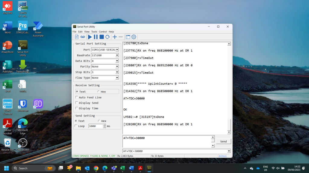
- The device will reply with ‘OK’. Then hit the reset button on the device to trigger this change. You will see an uplink then come through serial port utility every 30 or 60 seconds depending on which command was used.
1.5 LT-22222-L & RS485-LN
To access the AT Commands to change the configuration of your device you will need:
– A USB-TTL Converter
– 3 M-F DuPont Cables
– 3.5mm programming cable (provided with devices)
– A Phillips screwdriver
- Plug the 3.5mm programming cable into the PROG port on the device.
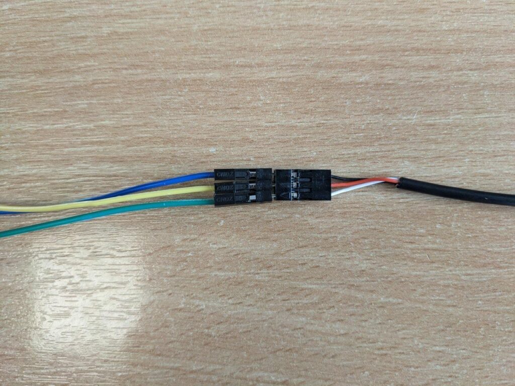
- Using the M-F Cables connect one end of the cables to the USB-TTL Converter as shown below:
- Then connect the other end of the cables to the corresponding pin receptors on the programming cable as shown below:
USB-TTL GND –> Black
USB-TTL RXD –> White
USB-TTL TXD –> Red
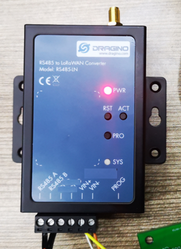
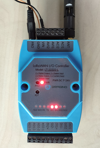
- Make sure your device is powered on. Both the LT-22222-L and the RS485-LN can be powered by a 7 ~ 24V DC power source. If the device is properly powered the Power LED will glow red. See below for connection methods:
RS485-LN
- Power Source VIN to RS485-LN VIN+
- Power Source GND to RS485-LN VIN-
LT-22222-L
- Power Source V+ to LT-22222-L VIN
- Power Source V- to LT-22222-L GND
- Plug the USB-TTL Converter into a USB port on your laptop and open Serial Port Utility. If you have a Windows laptop it should already be installed, if not you can install a copy here.
- On the left hand side, select the COM Port that you have plugged the USB-TTL converter into and make sure the rest of the fields match that of the image below:
- Click the play/start button to open the session.
- To begin communicating with the device may need to enter the device password (123456 or 12345678 as default- Newer models will have a unique AT Pin which can be found on the registration key sticker on the device box). Make sure to press the enter key before you press send as otherwise to command will not work.
- You can then enter any device specific or common commands to change the device configuration. In this example we will use the AT+TDC=(time in milliseconds) command to adjust the uplink interval.
- To see the current uplink interval use the AT Command: AT+TDC=?. Make sure to leave a new line after every AT Command entered. The device should then show 1200000 OK if the device is set to a 20min Uplink interval.
- To change the uplink interval enter: AT+TDC=’the required uplink interval in milliseconds’
For Example:
- AT+TDC=30000 – To change the uplink interval to 30 seconds
- AT+TDC=60000- To change the uplink interval to 60 seconds
- The device will reply with ‘OK’. Then hit the reset button on the device to trigger this change. You will see an uplink then come through serial port utility every 30 or 60 seconds depending on which command was used.
2.0 General Commands
These commands re universal across all devices. For device specific commands, please refer to the user manual of your device.
2.1 System Management Commands
2.1.1 Change Uplink Interval
Function: Change device uplink interval
AT Command: AT+TDC
| Command Example | Function | Response |
| AT+TDC=? | Shows the current uplink interval | 3000OKSo the interval here is 30000ms (30secs) |
| AT+TDC=60000 | Sets the uplink interval | OKThe interval has been set to 60000ms (60secs) |
2.1.2 Reboot End Node
Function: Reboot End Node to perform a new OTAA or ABP join
AT Command: ATZ
| Command Example | Function | Response |
| ATZ | Reset MCU | Device will reset and will show the booting info |
2.1.3 Reset to Factory Default
Function: Reset to factory default. The OTAA and ABP Keys will be preserved when running this command.
AT Command: AT+FDR
| Command Example | Function | Response |
| AT+FDR | Reset to factory default | Device will reset to factory default and will show the booting info |
2.1.4 Show Firmware Version
Function: Shows the firmware version and frequency plan of the device.
AT Commands: AT+VER
| Command Example | Function | Response |
| AT+VER=? | Shows the firmware version and frequency plan | 1.8.0 EU868OK |
2.1.5 Show System Configuration
Function: Shows system configuration.
AT Command: AT+CFG
| Command Example | Function | Response |
| AT+CFG | Shows full system configuration. | AT+DEUI = XX XX XX XX XX XX XX XX AT+DADDR=XXXXXXXX ………. AT+RX2WTO=X AT+CHS=868100000 OK |
2.2 Keys, ID & EUI Management
2.2.1 Application EUI (APPEUI)
Function: Get or set APPEUI
AT Command: AT+APPEUI
| Command Example | Function | Response | |
| AT+APPEUI=? | Shows the APPEUI | 00 B3 D5 00 00 00 00 00 OK | |
| AT+APPEUI=00 B3 D5 7E F0 00 4D 34 | Sets the APPEUI | OKThe APPEUI has been set to 00 B3 D5 7E F0 00 4D 34 | |
2.2.2 Application Key (APPKEY)
Function: Get or set APPKEY
AT Command: AT+APPKEY
| Command Example | Function | Response | |
| AT+APPKEY=? | Shows the APPKEY | 00 35 55 55 22 23 55 53 43 24 23 42 34 35 35 35OK | |
| AT+APPKEY= 00 35 55 55 22 23 55 53 43 24 23 42 34 35 35 35 | Sets the APPKEY | OKThe APPEUI has been set to 00 35 55 55 22 23 55 53 43 24 23 42 34 35 35 35 | |
2.2.3 Application Session Key (APPSKEY)
Function: Get or set APPSKEY
AT Command: AT+APPSKEY
| Command Example | Function | Response | |
| AT+APPSKEY=? | Shows the APPSKEY | 00 7D DC 73 33 D3 EB 9E 14 38 D5 A4 3E 62 5B E2OK | |
| AT+APPSKEY= 00 7D DC 73 33 D3 EB 9E 14 38 D5 A4 3E 62 5B E2 | Sets the APPSKEY | OKThe APPSKEY has been set to 00 7D DC 73 33 D3 EB 9E 14 38 D5 A4 3E 62 5B E2 | |
2.2.4 Device Address (DEVADDR)
Function: Get or set DEVADDR
AT Command: AT+DADDR
| Command Example | Function | Response | |
| AT+DADDR=? | Shows the DEVADDR | A8 40 41 FFOK | |
| AT+DADDR= A8 40 41 FF | Sets the DEVADDR | OKThe DEVADDR has been set to A8 40 41 FF | |
2.2.5 Device EUI (DEVEUI)
Function: Get or set DEVEUI
AT Command: AT+DEUI
| Command Example | Function | Response | |
| AT+DEUI=? | Shows the DEVEUI | 00 44 34 22 33 45 55 55 OK | |
| AT+DEUI= A8 40 41 FF FF 12 34 56 | Sets the DEVEUI | OKThe DEVEUI has been set to A8 40 41 FF FF 12 34 56 | |
2.2.6 Network ID (NWKID)
Function: Get or set NWKID
AT Command: AT+NWKID
| Command Example | Function | Response | |
| AT+NWKID=? | Shows the Network ID | A8 40 41 FFOK | |
| AT+NWKID= A8 40 41 FF | Sets the Network ID | OKThe DEVADDR has been set to A8 40 41 FF | |
2.2.7 Network Session Key (NWKSKEY)
Function: Get or set NWKSKEY
AT Command: AT+NWKSKEY
| Command Example | Function | Response | |
| AT+NWKSKEY=? | Shows the NWKSKEY | 00 4F 19 25 52 CE 97 09 D7 FA 84 71 DB 51OK | |
| AT+NWKSKEY= A8 40 41 FF FF 12 34 56 00 01 02 04 05 06 06 07 | Sets the NWKSKEY | OKThe NWKSKEY has been set to A8 40 41 FF FF 12 34 56 00 01 02 04 05 06 06 07 | |
2.3 Joining & sending data on a LoRaWAN Network
2.3.1 Confirmation Mode
Function: Get or set the confirmation mode (0-1).
Before DR-LWS-007 software stack.
AT Command: AT+CFM
| Command Example | Function | Response |
| AT+CFM=? | Shows the Confirmation mode | 0OK |
| AT+CFM=1 | Sets the Confirmation mode | OKThe CFM has been set to 1 |
| AT+CFM=2 | Sets the Confirmation mode | OKThe CFM has been set to 2 |
After DR-LWS-007 software stack.
AT Command: AT+CFM
| Command Example | Function | Response |
| AT+CFM=1,0,0Value1 | Confirmed uplink | 1OK |
| AT+CFM=0,?,0Value2 | Sets max retry level, range: 0~-7 | 0~7OKThe Max retry level has been set to 0~7 |
| AT+CFM=0,0,1Value3 | Sets the uplink FCnt to increase by 1 for each try | 1OKThe uplink FCnt has been set to increase by 1 for each try |
2.3.2 Confirmation Status
Function: Gets the confirmation status of the last AT+SEND (0-1).
AT Command: AT+CFS
| Command Example | Function | Response |
| AT+CFS=? | Gets confirmation status | 0OK |
2.3.3 Join LoRa Network
Function: Joins the LoRa Network.
AT Command: AT+JOIN
| Command Example | Function | Response |
| AT+JOIN=? | Gets information | AT+JOIN: Join NetworkOK |
2.3.4 LoRa Network Join Mode
Function: Gets or sets the LoRa Network Join Mode.
AT Command: AT+NJM
| Command Example | Function | Response |
| AT+NJM=? | Gets network join mode | 1OK |
| AT+NJM=0 | Sets the network join mode | OKThe NJM has been set to 0 |
| AT+NJM=2 | Sets the network join mode | OKThe NJM has been set to 2 |
2.3.5 LoRa Network Join Status
Function: Gets the LoRa Network Join Status.
AT Command: AT+NJS
| Command Example | Function | Response |
| AT+NJS=? | Gets the join status | 0OK |
2.3.6 Print last received data in raw format
Function: Prints the last received data in raw format (<port:data>).
AT Command: AT+RECV
| Command Example | Function | Response |
| AT+RECV=? | Prints the last received data in the raw format | 0:OK |
2.3.7 Print last received data in binary format
Function: Prints the last received data in binary format (<port:data>).
AT Command: AT+RECVB
| Command Example | Function | Response |
| AT+RECVB=? | Prints the last received data in the binary format | 2: 0010OK |
2.3.8 Send Text Data
Function: Sends text data (<port:data>).
AT Command: AT+SEND
| Command Example | Function | Response |
| AT+SEND=12:hello world | Sends text data along with the application port | OK |
2.3.9 Send Hexadecimal Data
Function: Sends hexadecimal data (<port:data>).
AT Command: AT+SENDB
| Command Example | Function | Response |
| AT+SENDB=12:ABCDEF0123456789 | Sends hexadecimal data along with the application port | OK |
2.4 LoRaWAN Network Management
2.4.1 Adaptive Data Rate (ADR)
Function: Get or set the ADR setting (0: off, 1: on).
AT Command: AT+ADR
| Command Example | Function | Response |
| AT+ADR=? | Gets the ADR setting | 1OK |
| AT+ADR=0 | Sets the ADR setting | OKThe ADR setting has been set to 0: Off |
| AT+ADR=1 | Sets the ADR setting | OKThe ADR setting has been set to 1: On |
2.4.2 LoRa Class
Function: Get or set the device class (Dragino products currently only support class A & C).
AT Command: AT+CLASS
| Command Example | Function | Response |
| AT+CLASS=? | Gets the device class | AOK |
| AT+CLASS=C | Sets the device class | OKThe device class has been set to C |
Note: Run AT+FDR Before running AT+CLASS=C
2.4.3 Duty Cycle Setting
Function: Get or set the ETSI Duty Cycle setting (0=disabled, 1=enabled -Only for testing).
AT Command: AT+DCS
| Command Example | Function | Response |
| AT+DCS=? | Gets the ETSI duty cycle setting | 1OK |
| AT+DCS=0 | Sets the ETSI duty cycle setting | OKThe ETSI duty cycle setting has been set to 0: Disabled |
2.4.4 Data Rate
Function: Get or set the Data Rate (0-7 corresponding to DR_X).
AT Command: AT+DR
| Command Example | Function | Response |
| AT+DR=? | Gets the Data rate | 5OK |
| AT+DR=2 | Sets the Data rate | OKThe data rate has been set to 2 |
Note: Users need to use command AT+ADR=0 to set the ADR to 0 first. Otherwise the device will respond to the servers ADR command and change the DR according to the servers auto-adjustment.
Data Rate specifies the Spreading Factor- The mapping varies in different frequency bands.
2.4.5 Frame Counter Downlink
Function: Get or set the Frame Counter Downlink.
AT Command: AT+FCD
| Command Example | Function | Response |
| AT+FCD=? | Gets the Frame Counter Downlink. | 0OK |
| AT+FCD=10 | Sets the Frame Counter Downlink. | OKThe system will write the new value to FCD. |
2.4.6 Frame Counter Uplink
Function: Get or set the Frame Counter Uplink.
AT Command: AT+FCU
| Command Example | Function | Response |
| AT+FCU=? | Gets the Frame Counter Uplink. | 0OK |
| AT+FCU=10 | Sets the Frame Counter Uplink. | OKThe system will write the new value to FCU. |
2.4.7 Join Accept Delay 1
Function: Get or set the Join Accept delay between the end of the TX and the Join RX Window 1 (RX1) in ms.
AT Command: AT+JN1DL
| Command Example | Function | Response |
| AT+JN1DL=? | Gets the Join Accept delay | 5000OK |
| AT+JN1DL=10000 | Sets the Join Accept delay | OKThe join accept delay has been set to 10000ms |
2.4.8 Join Accept Delay 2
Function: Get or set the Join Accept delay between the end of the TX and the Join RX Window 2 (RX2) in ms.
AT Command: AT+JN2DL
| Command Example | Function | Response |
| AT+JN2DL=? | Gets the Join Accept delay | 6000OK |
| AT+JN2DL=20000 | Sets the Join Accept delay | OKThe join accept delay has been set to 20000ms |
2.4.9 Public Network Mode
Function: Get or set the public network mode (0:off, 1:on).
A public LoRaWAN network uses 0x34 as a sync-word. Default settings: PNM=1
AT Command: AT+PNM
| Command Example | Function | Response |
| AT+PNM=? | Gets the public network mode | 1OK |
| AT+PNM=1 | Sets to use public network mode.Sets syncword=0x34 | OKSystem will write new value to PNM |
| AT+PNM=0 | Sets to use private network mode.Sets syncword=0x12 | OK |
Note: If you are building your own LoRaWAN Server but still use syncword=0x34, this is still considered a public network.
2.4.10 Receive Delay 1
Function: Get or set the delay between the end of TX and the RX1 Window in ms.
AT Command: AT+RX1DL
| Command Example | Function | Response |
| AT+RX1DL=? | Gets the receive delay | 1000OK |
| AT+RXDL1=1500 | Sets the receive delay | OKThe receive accept delay has been set to 1500ms |
2.4.11 Receive Delay 2
Function: Get or set the delay between the end of TX and the RX2 Window in ms.
AT Command: AT+RX2DL
| Command Example | Function | Response |
| AT+RX2DL=? | Gets the receive delay | 2000OK |
| AT+RXDL2=2500 | Sets the receive delay | OKThe receive accept delay has been set to 2500ms |
2.4.12 RX2 Window Data Rate
Function: Get or set the RX2 window data rate (0-7 corresponding to DR_X).
AT Command: AT+RX2DR
| Command Example | Function | Response |
| AT+RX2DR=? | Gets the RX2 window data rate | 2OK |
| AT+RXDR=6 | Sets the RX2 window data rate | OKThe RX2 window data rate has been set to 6 |
2.4.13 RX2 Window Frequency
Function: Get or set the RX2 window frequency.
AT Command: AT+RX2FQ
| Command Example | Function | Response |
| AT+RX2FQ=? | Gets the RX2 window frequency | 2OK |
| AT+RX2FQ=434665000 | Sets the RX2 window data frequency | OKThe RX2 window frequency has been set to 434665000 |
2.4.14 Transmission Power
Function: Get or set the transmission power (0-5, MAX:0, MIN:5- According to LoRaWAN Spec or 40=10dB, 41=11dB…50=20dB which is out of LoRaWAN Spec).
AT Command: AT+TXP
| Command Example | Function | Response |
| AT+TXP=? | Gets the Transmission power | 0OK |
| AT+TXP=1 | Sets the Transmission power | OKThe Transmission power has been set to 1 |
Note: Transmission power might be changed by the ADR from the LoRaWAN server. So when manually changing the TXP also remember to use AT+ADR=0.
2.4.15 RSSI of the Last Received Packet
Function: Get the RSSI of the last received packet.
AT Command: AT+RSSI
| Command Example | Function | Response |
| AT+RSSI=? | Gets the RSSI of the last received packet | 0OK |
2.4.16 SNR of the Last Received Packet
Function: Get the SNR of the last received packet.
AT Command: AT+SNR
| Command Example | Function | Response |
| AT+SNR=? | Gets the SNR of the last received packet | 0OK |
2.4.17 Application Port
Function: Get or set the Application Port.
AT Command: AT+PORT
| Command Example | Function | Response |
| AT+PORT=? | Gets the Application Port | 21OK |
| AT+PORT=21 | Gets the Application Port | OKThe Application port has been set to 21 |
2.4.18 Single Channel Mode
Function: Get or set the Frequency (Unit:Hz) for Single Channel Mode.
AT Command: AT+CHS
| Command Example | Function | Response |
| AT+CHS=? | Gets the Single Channel Mode | 0OK |
| AT+CHS=868100000 | Gets the Single Channel Mode | OKThe single channel mode has been set to 868100000 |
2.4.19 Eight Channel Mode
Function: Get or set Eight Channel Mode. Only for bands: US915, AU915 & CN470.
AT Command: AT+CHE
| Command Example | Function | Response |
| AT+CHE=? | Gets the Eight Channel Mode | 1902.3 902.5 902.7 902.9 903.1 903.3 903.5 903.7OK |
| AT+CHE=1 | Gets the Eight Channel Mode | OKThe eight channel mode has been set to 1 |
2.4.20 RX1 Window Timeout
Function: Get or set the number of symbols to detect and timeout from the RX1 Window (0-255).
AT Command: AT+RX1WTO
| Command Example | Function | Response |
| AT+RX1WTO=? | Gets the RX1 Window Timeout | 14OK |
| AT+RX1WTO=60 | Gets the RX1 Window Timeout | OKThe RX1 window timeout has been set to 60 |
2.4.21 RX2 Window Timeout
Function: Get or set the number of symbols to detect and timeout from the RX2 Window (0-255).
AT Command: AT+RX2WTO
| Command Example | Function | Response |
| AT+RX2WTO=? | Gets the RX1 Window Timeout | 7OK |
| AT+RX2WTO=20 | Gets the RX1 Window Timeout | OKThe RX2 window timeout has been set to 20 |
2.4.22 Uplink Dwell Time
Function: Get or set the uplink dwell time. Only for AS923 & AU915.
AT Command: AT+DWELLT
| Command Example | Function | Response |
| AT+DWELLT=? | Gets the Uplink Dwell Time | 1OK |
| AT+DWELLT=0 | Gets the Uplink Dwell Time | OKThe uplink dwell time has been set to 0 |
2.4.23 Packet Receiving Response Level
Function: Get or set the packet receiving response level. This feature is used to set compatible with different LoRaWAN servers. If the RPL doesn’t match, the user will see strange messages in the server portal.
RPL Value:
- -AT+RPL=0: The device won’t immediately reply to any downlink commands from the platform
- AT+RPL=1: The device will immediately reply to unconfirmed data downlinks. Payload is 0x00
- AT+RPL=2: The device will immediately reply to confirmed data downlinks. Payload is 0x00 and the required response header for this command.
- AT+RPL=3: The device will immediately reply to MAC commands. Payload is 0x00 and the required response header for this command.
- AT+RPL=4: The device will immediately reply to confirmed data downlinks & MAC commands. Payload is 0x00 and the required response header for these 2 commands.
Case Analysis:
- For Class A devices, AT+RPL=0 is ok. This is the default setting.
- For Class C devices using ChirpStack, AT+RPL=4 will need to be used as ChirpStack requires immediate replies to MAC commands.
- For Class C devices using TTI, AT+RPL=4 will need to be used as TTI requires immediate replies to MAC commands & confirmed data downlink.
AT Command: AT+RPL
| Command Example | Function | Response |
| AT+RPL=? | Gets the packet receiving response level | 1OK |
| AT+RPL=0 | Gets the packet receiving response level | OKThe packet receiving response level has been set to 0 |
2.4.24 Control NBTrans in Unconfirmed Uplink Mode
Function: LWS007 NBTrans: set retransmission packets.
AT Command: AT+SETMAXNBTRANS
| Command Example | Function | Response |
| AT+SETMAXNBTRANS=1,0 | Value 1: Sets the maximum NBTrans. | 1OK |
| AT+SETMAXNBTRANS=?,1 | Value 2: 0: Uplink FCnt doesn’t change for each NBTrans1: uplink FCnt increases by 1 for each NBTrans | 1OK |
2.4.25 Device Offline Rejoining (LWS007)
AT+DDETECT= <Flag>, <ACK_Timeout_1>, <ACK_Timeout_2> (Default Value: AT+DDETECT=1,1440,2880)
- ACK_Timeout_1: Unit: min
- ACK_Timeout_2: Unit: min
AT Command: AT+DDETECT
| Command Example | Function | Response |
| AT+DDETECT= 1,1440,2880Value1 | Enable online detection | 1OK |
| AT+DDETECT=1,?,2280Value2 | Online detection packet sending time | OK |
| AT+DDETECT= 1,1440,?Value3 | Processes re-join | OK |
2.4.26 Request the Server to send an ACK
AT Command: AT+PNACKMD
| Command Example | Function | Response |
| AT+PNACKMD=1 | If the node uploads the ACK as confirmed, it will request the server to send an ACK. If the server ACK is not received, the node will upload the packets that have not received the ACK the next time it receives the ACK. | 1OK |
| AT+PNACKMD=0 | Off request the server to send an ACK | 0OK |
2.4.27 Request the Server to send an ACK
AT Command: AT+RJTDC
| Command Example | Function | Response |
| AT+RJTDC=? | Shows the re-join data transmission interval in mins | 30OK |
| AT+RJTDC=60 | Sets the re-join data transmission interval in mins | OKThe re-join data transmission has been set to 60 mins |